

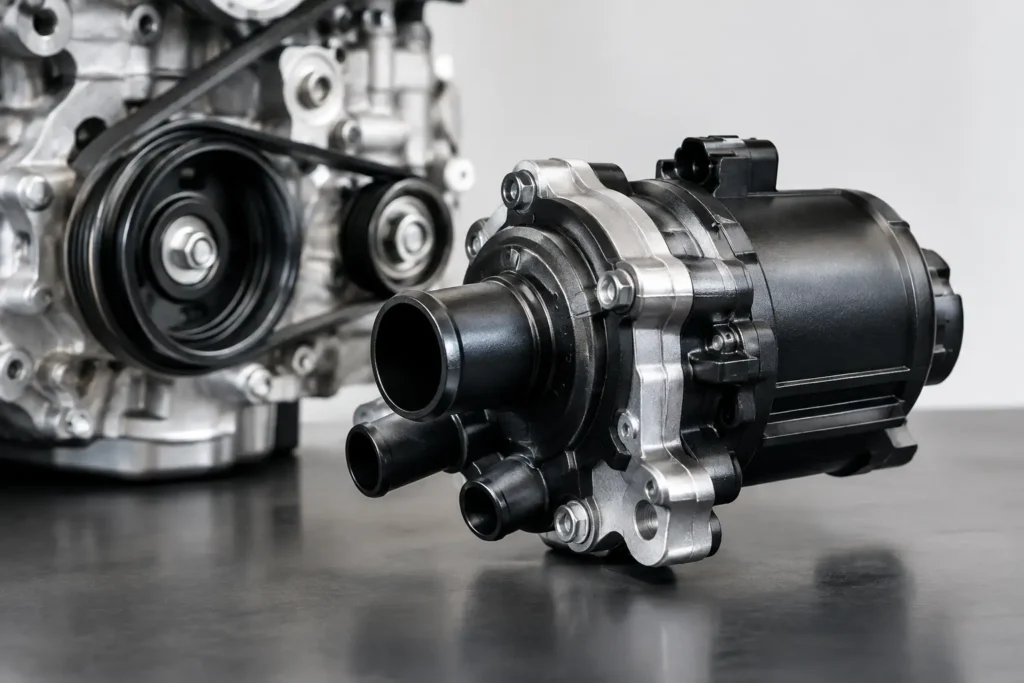
A mechanical water pump is tied to engine speed. That works well on a standard road car, but it is a compromise once the engine spends its life at high rpm, sitting in staging lanes, drifting at low vehicle speed, or running a large turbo setup. Electric water pumps separate coolant flow from crank speed, giving the builder direct control over one of the engine’s most critical systems.
For a serious street, drift or race build, the point is not simply to fit the biggest pump available. The correct pump, controller, radiator and hose layout must work as one system. Get that right and you gain stable temperatures, reduced parasitic drag and better cooling control where a belt-driven pump is least effective.
Why fit an electric water pump?
A conventional pump speeds up with the engine. At idle, when airflow through the radiator is limited and heat can build quickly, coolant flow is at its lowest. At high rpm, the pump may move more coolant than the system needs, consuming power and potentially creating cavitation or excess pressure in an unsuitable setup.
An electric unit runs at the speed commanded by its controller. It can maintain useful circulation in the pits, during a hot restart or after a hard pull, regardless of engine speed. Many systems also offer staged pump control, fan triggering and after-run operation. After the ignition is switched off, the pump can continue circulating coolant to reduce localised heat soak around the cylinder head and turbocharger.
There is also a packaging benefit. Removing a mechanical pump can free space at the front of the engine, simplify an accessory drive, and help on custom installations where the engine sits close to a chassis rail, radiator or dry-sump hardware. That said, an electric conversion adds wiring, mounting work and another electrical load. It is a performance upgrade that rewards proper planning, not a universal shortcut.
Choosing electric water pumps by application
Pump choice starts with the engine’s heat output, coolant volume, restriction in the system and intended use. A compact four-cylinder track car with a well-sized radiator has different requirements from a high-boost six-cylinder drift car or a V8 circuit car running extended sessions.
Flow rate is not the only number
Manufacturers commonly quote a maximum flow figure, but that number is measured under specific conditions. Real flow falls as restriction rises through the radiator core, thermostat housing, cylinder-head passages, hoses, bends and fittings. A high-flow rating alone does not guarantee that a pump suits the installation.
Look at the pump’s pressure capability and its published flow curve where available. Long coolant runs, rear-mounted radiators, restrictive heater circuits and densely packaged turbo engines all place greater demand on the pump. On the other hand, excessive pump capacity can make it harder to control flow and may expose weaknesses in old hoses, radiator tanks or sealing surfaces.
For most performance builds, match the pump to the engine family and cooling layout rather than buying on headline litres-per-minute alone. A reputable pump manufacturer with clear application guidance is worth more than an unknown unit with ambitious claims.
Street, drift and race use need different priorities
A fast road car benefits from controlled warm-up, quieter operation and reliable after-run cooling. A controller that varies pump speed based on coolant temperature is usually the sensible route, particularly if the car sees regular traffic.
Drift cars need strong low-speed cooling performance. They repeatedly generate high engine load with limited natural airflow, then sit stationary between runs. Pump control must work alongside high-capacity fans, proper shrouding and a radiator that receives clean air. A bigger pump will not cure poor ducting or fans wired to run too late.
For race cars, durability and serviceability move to the front of the list. Choose a pump with proven continuous-duty capability, secure motorsport-grade connectors and a mounting position that remains accessible. A spare pump or service kit can be sensible for teams running long events, especially when a retirement over a small cooling component is unacceptable.
Building the cooling system around the pump
An electric pump is one part of a complete circuit. Treating it as a bolt-on component is how conversions develop air locks, inconsistent temperatures and leaks at the worst possible time.
The pump should generally sit low in the system and close to the radiator outlet, where it can push cool coolant through the engine. This helps keep the inlet flooded and reduces the risk of cavitation. Follow the pump manufacturer’s mounting instructions, particularly for orientation, vibration isolation and minimum inlet hose size.
Use smooth-radius hose routing wherever space allows. Sharp bends, necked-down joiners and poorly chosen fittings restrict flow. For fabricated systems, aluminium hard lines can tidy a bay and protect hoses near exhaust components, but they need proper bead rolls, quality silicone joiners and clamps capable of holding pressure through repeated heat cycles.
A header tank or swirl pot positioned at the highest practical point is often essential on custom layouts. It gives trapped air somewhere to collect and provides a controlled fill point. This matters even more with rear radiators, tilted engines, remote turbo coolant lines or heater circuits that sit above the main engine water passages.
Do not remove the thermostat without a reason. The thermostat controls warm-up and, in many engines, directs coolant through different paths as temperature changes. Some electric-pump systems use a dedicated thermostat housing, restrictor or electronic control strategy instead. The correct answer depends on the engine and pump design. Copying a race-car setup without understanding its bypass circuit can create slow warm-up or uneven cylinder-head temperatures on the road.
Wiring and control are part of the installation
Electric pumps draw meaningful current, especially at start-up and full speed. Wire them with correctly sized cable, a dedicated fuse and a relay or controller rated for the load. Do not power a high-output pump through an undersized switched feed or an ageing auxiliary circuit.
A proper installation should account for the following:
- A fused supply sized to the pump manufacturer’s stated current draw.
- A reliable ground connected to clean chassis metal or directly to the battery negative where appropriate.
- Switched ignition control, plus a controller or ECU output for variable-speed operation.
- Fan control that responds to coolant temperature rather than an arbitrary dashboard switch.
- A safe after-run strategy that will not flatten the battery after every heat cycle.
Modern ECUs can often control a pump through a pulse-width-modulated output, switched relay logic or a dedicated auxiliary channel. This makes it possible to run lower speed during warm-up, increase flow as temperatures rise, and command fans independently. Confirm the output type and current capacity before connecting anything. An ECU low-side output may need to trigger a relay rather than power the pump directly.
Use a coolant temperature sensor placed where it reflects genuine engine temperature. A sensor in a stagnant section of pipe or too close to the radiator outlet can make the system react late or cycle unpredictably. For critical builds, logging coolant temperature, inlet-air temperature and fan state after each session gives far better information than watching the gauge once the problem has already appeared.
Common mistakes that cost engines
The most frequent mistake is chasing a pump to solve an airflow problem. If the radiator is too small, the core is blocked, the fans are poorly shrouded, or hot air cannot exit the engine bay, increasing coolant flow alone will not save the temperature control.
Another is inadequate bleeding. Fill slowly, raise the front of the vehicle if needed, open bleed points, run the pump according to the manufacturer’s procedure and let the system cool fully before checking the level again. Air pockets can cause sudden gauge swings and local boiling even when the radiator feels full.
Also inspect the rest of the system before adding pressure and flow. Replace tired hoses, questionable clamps and cracked expansion tanks. Check the radiator cap rating, because it sets system pressure and affects coolant boiling point. A higher-pressure cap is not automatically better if the radiator or heater matrix cannot tolerate it.
Finally, keep a mechanical fallback in mind. Some engines use the original pump housing as part of the front cover or rely on it for belt routing. An electric conversion may require a blanking plate, an idler solution or a purpose-built housing. Confirm every mechanical detail before dismantling a running car.
Spec the system before ordering parts
Measure hose diameters, note radiator port sizes, identify the thermostat and bypass arrangement, and calculate where the pump, controller and header tank will sit. Then select the fittings, hose, clamps, wiring protection and mounting hardware to suit the complete layout. ProSpeed Parts can supply the specialised cooling and fluid-system hardware needed to build it properly, rather than forcing a custom installation around generic parts.
A well-specified electric pump setup gives you control when the engine is working hardest and when airflow is weakest. Before the first hard run, pressure-test the system, verify fan and pump trigger temperatures, and log a full heat cycle. Cooling reliability is built in the workshop, long before it is proven on circuit.