

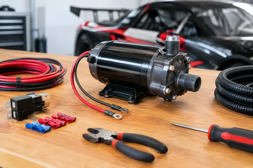
A mechanical water pump follows engine speed whether the engine needs maximum coolant flow or not. An electric pump gives you control, frees up parasitic drag and can continue circulating coolant after shut-down. But the gains disappear quickly if the wiring is undersized, unfused or controlled by a weak ignition circuit. If you searched for how to wire electric water pump hardware correctly, treat it as a high-current cooling circuit, not a simple accessory feed.
For track cars, drift builds and modified street engines, the target is simple: stable coolant temperature, dependable operation and wiring that remains serviceable after heat, vibration and repeated use. The right pump is only half the system.
Start with the pump’s real electrical demand
Do not choose cable, relay or fuse ratings from a generic internet diagram. Read the pump manufacturer’s current specification first. Electric water pumps vary substantially: a compact auxiliary unit may draw only a few amps, while a main engine pump can draw 10 to 20 amps continuously and significantly more during start-up.
Use the specified running current as the baseline, then allow sensible headroom for inrush current and hot under-bonnet conditions. A circuit that survives a bench test can still become unreliable when the alternator is charging, the fan switches on and the wiring is sitting beside a turbo manifold.
Cable length matters as much as cable size. Long runs create voltage drop, and reduced voltage slows the pump or makes its speed control inconsistent. For a typical front-engine car with the battery in the engine bay, a quality 2.5 mm² automotive cable may suit a modest pump. Higher-current pumps, rear-mounted batteries and longer cable routes often justify 4 mm² or 6 mm² cable. Confirm against the pump instructions and calculate for the full circuit length, including the earth path.
Avoid household cable and vague AWG-to-metric assumptions. Use proper automotive thin-wall cable or high-temperature cable where required, with insulation suitable for engine-bay heat and fluids.
The correct electric water pump wiring layout
The dependable arrangement is a fused battery supply feeding a relay, with the relay supplying the pump. A low-current switched source, controller or ECU output then operates the relay coil. This keeps pump current out of the ignition switch, ECU auxiliary output and lightweight dashboard wiring.
The basic path is:
- battery positive to an inline fuse located close to the battery
- fused supply to relay terminal 30
- relay terminal 87 to water pump positive terminal
- water pump negative terminal to a clean chassis or engine earth, or directly to battery negative
- ignition-switched feed, ECU output or controller output to the relay coil circuit
Use a quality four-pin or five-pin automotive relay with a continuous rating that exceeds the pump’s expected current. A 30 A relay is common, but relay quality matters more than the number stamped on the casing. For a high-draw pump or endurance application, a sealed motorsport relay, relay carrier or solid-state power module can be the better choice.
Fuse the cable, not just the component. The fuse must protect the smallest wire in the power circuit, while remaining high enough to tolerate normal pump start-up. As a starting principle, choose a fuse above normal operating current but below the safe current rating of the installed cable. If the fuse blows, investigate the cause. Replacing it with a larger fuse without checking the circuit is how melted looms start.
Choose the right control strategy
A pump can run whenever the ignition is on, but that is not always the best setup. It works for straightforward race cars where predictability matters more than convenience, and it removes one potential control failure. The downside is unnecessary current draw and coolant circulation during every key-on period.
A thermostatic controller is a practical standalone option. It can switch the pump at a chosen temperature and, depending on the controller, run it after the engine is shut down. That after-run feature helps prevent localised heat soak around the cylinder head and turbocharger after a hard session.
For ECU-controlled builds, a programmable auxiliary output offers more precise management. The ECU can activate the relay above a coolant temperature threshold, control a compatible PWM pump, or retain pump operation for a defined period after key-off. This approach is particularly useful where fan control, boost strategies and engine protection functions are already handled by the ECU.
Check the output type before connecting anything. Some ECUs provide a low-side output that switches an earth, rather than a 12 V positive signal. That output should usually trigger the relay coil, not supply the pump directly. Configure fail-safe behaviour carefully: if a temperature sensor fails or the ECU loses its reference, the safest response for many competition applications is to command the pump on.
Earths, connectors and cable routing decide reliability
Most water pump faults blamed on the pump are voltage-drop or earth faults. A painted bracket, corroded chassis point or undersized earth cable can leave a healthy pump underpowered. Run an earth cable equal to the positive cable size where possible. Terminate it at bare, clean metal with a serrated washer and corrosion protection, or route it directly back to battery negative in a dedicated race loom.
Use crimp terminals sized for both the conductor and stud. A proper ratchet crimper delivers a secure joint; pliers and a crush-style terminal do not. Adhesive-lined heat shrink, sealed connectors and strain relief are worth fitting when the car sees wet roads, wash-downs or vibration. Solder has a place in controlled loom work, but do not create a long, rigid soldered section that will fatigue beside an engine.
Route the harness away from exhausts, manifolds, belts, steering joints and sharp alloy edges. Where it must pass through bulkheads or brackets, fit grommets and abrasion sleeve. Support the loom at regular intervals with P-clips rather than cable ties alone. Cable ties are useful, but they are not a substitute for proper mounting on a car that sees kerbs, heat cycles and engine movement.
Wire an electric water pump with fans and after-run in mind
The pump and radiator fans should be treated as related systems, not automatically placed on one shared circuit. Each high-current load needs its own appropriately fused supply and relay. Combining them can overload a relay, complicate fault-finding and leave both systems disabled by one blown fuse.
If your controller or ECU offers separate outputs, set the pump to begin circulation before the fan threshold. Coolant flow must be present for the radiator and fan package to do its job efficiently. On a turbocharged car, consider a pump after-run strategy, but confirm that the pump, battery capacity and controller are designed for it. A car stored for weeks with an overactive after-run function can leave you with a flat battery.
Mechanical cooling-system details still matter. An electric pump will not fix trapped air, a blocked radiator, incorrect pulley-era hose routing, inadequate ducting or a poor expansion-tank position. Bleed the system properly, verify heater-circuit flow where applicable and make sure the pump is installed in the direction specified by its manufacturer.
Test the circuit before relying on it
Before starting the engine, check continuity, terminal security and fuse size. Power the pump and listen for a clean, consistent motor note. Measure voltage at the pump terminals with the pump running. It should be close to battery voltage; a notable drop points to undersized cable, poor connections or a weak earth.
Then test it with the engine hot. Confirm that the pump triggers at the intended temperature, fans operate independently at their set point and the relay remains cool. If ECU-controlled, simulate the relevant output condition and verify the logic rather than assuming the calibration is correct.
For serious builds, label the fuse and relay, keep a wiring diagram with the vehicle paperwork and carry the correct spare fuse. ProSpeed Parts customers building street, drift or race cars know that quick diagnosis at an event is worth far more than saving a few minutes during installation.
A well-wired electric water pump is quiet insurance for the engine. Build the circuit with the same care as your fuel system or oil-pressure protection, and it will keep doing its job when the coolant temperature starts to matter most.