

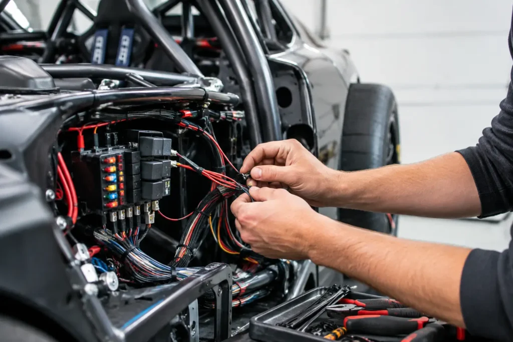
A failed £2 terminal can end a race weekend faster than a missed shift. Heat, vibration, kerb strikes, fluid exposure and rapid fault-finding put far more pressure on a competition loom than a standard road-car harness. This race car wiring guide focuses on the decisions that make a build reliable, serviceable and safe when it matters.
Start the race car wiring guide with a circuit plan
Do not begin by cutting cable. Begin with the electrical load list and a simple wiring diagram that shows every power source, fuse, relay, switch, sensor, actuator and ground point. It does not need to be a work of art. It does need to reflect the vehicle you are actually building, including future additions such as a data logger, cooling fan override, wideband controller, gearbox pump or additional lighting.
Split the system into logical circuits. The main battery and starter circuit should remain separate from the ECU and engine-management feed. Fuel pumps, fans, ignition, injectors, dash, lights and auxiliary systems should each have their own protected supply where practical. This makes diagnosis faster and reduces the chance that one fault takes out the whole car.
A race car does not always need every circuit found on a road car. Removing redundant comfort, infotainment and convenience wiring reduces weight and complexity. But avoid stripping the loom blindly. Many modern engines rely on specific sensor references, shielded signal wiring, CAN connections and switched supplies. If an ECU pinout says a circuit is required, treat it as required until the engine management documentation proves otherwise.
Choose cable by current, length and environment
Cable sizing is not about using the thickest wire everywhere. Oversized cable adds cost, weight and routing difficulty; undersized cable creates voltage drop, heat and failure. Choose conductor size according to continuous current draw, cable run length and the environment around it.
High-current loads such as starter motors, alternators, electric power steering pumps and large cooling fans need appropriately sized battery cable and terminals. Fuel pumps, coils and fan circuits can draw substantial current too, particularly during start-up. Long runs need more attention because resistance increases with length. A pump that sees low voltage at the rear of the car may still run, but fuel delivery and engine safety can suffer at full load.
Use quality automotive or motorsport-rated thin-wall cable for general circuits, with insulation suited to heat, oil and abrasion. In high-temperature areas around the turbocharger, manifold or exhaust tunnel, use proper heat protection and route the loom away from radiant heat rather than relying on sleeve alone. Sleeve is protection, not permission to run cable through a bad location.
Sensor wiring needs a different approach. Crank, cam, knock and certain pressure or temperature signals may require twisted pair or shielded cable depending on the ECU manufacturer’s instructions. Keep low-level sensor wiring away from coils, injectors, alternator wiring and pump feeds. Electrical noise can look like a tuning problem, a trigger fault or an intermittent sensor failure.
Build a power distribution system you can diagnose
A clean distribution layout saves time every time the car is serviced. Place the battery isolator, main fuse protection, relays and fuse box where they are accessible without removing half the interior. A neatly mounted power distribution module can reduce relay and fuse complexity, but conventional relays and fuse holders remain a dependable, cost-effective option for many builds.
Every unfused cable connected directly to the battery is a risk. Protect main feeds close to the battery wherever the application allows. The fuse rating must protect the cable, not merely stop the fuse blowing during normal operation. If a circuit repeatedly blows its fuse, do not simply fit a larger one. Find the short, excessive load or poor connection first.
Relays allow a low-current switch, ECU output or control panel to operate a higher-current device. They are particularly useful for pumps, fans, lighting and horns. Use relays with a current rating that suits the load, and consider sealed units where the installation is exposed to spray, dust or heat.
A master kill switch should be selected and wired for the vehicle’s electrical system, not fitted as a visual motorsport accessory. Depending on the regulations and the car’s charging arrangement, the isolator may need to stop the engine as well as isolate battery power. Check the rules for the championship, venue and scrutineering body before finalising the layout.
Grounding is where reliable builds are won
Many intermittent electrical faults are ground faults. Paint, powder coat, corrosion, anodised brackets and loose fasteners all add resistance where you least want it. Establish a main chassis ground close to the battery, use a substantial engine-to-chassis ground strap, and create a planned ground strategy for the ECU, sensors and accessories.
For engine management, follow the ECU manufacturer’s grounding instructions exactly. ECU power grounds commonly need to go directly to the engine block or cylinder head, while sensor grounds should return through the ECU’s dedicated sensor-ground pins. Joining these circuits randomly to a dashboard bar can introduce noise and unstable readings.
Prepare ground points properly: remove coating to bare metal, use the correct terminal, secure it with suitable hardware and protect the finished joint against corrosion. A star washer can help bite into the metal, but it is not a substitute for a clean contact surface and correct cable size. Label ground points in the wiring diagram so another technician can test them quickly.
Route, protect and terminate the loom properly
The best wiring diagram will not rescue a loom that rubs through on a bulkhead edge. Route cables with movement, heat and maintenance in mind. Leave controlled service loops at removable panels and engine connections, but do not leave loose coils that can snag or retain heat. Support the loom at regular intervals with P-clips or purpose-made mounts rather than relying on cable ties alone.
Use grommets wherever wiring passes through metal or composite panels. Add abrasion sleeve, conduit or braided protection where the loom runs near sharp edges, moving suspension components or drivetrain parts. Keep connectors positioned where they can be reached and unplugged, not buried behind an intake pipe or welded brace.
Terminations deserve the same attention as expensive engine parts. Use quality crimp terminals and the correct crimp tool for the terminal system. A proper crimp is mechanically secure and electrically sound. Solder has a place in controlled repairs and electronics work, but a soldered joint in a high-vibration loom can become stiff and fatigue if it is not correctly supported.
Heat-shrink should seal and strain-relieve joints, especially in exposed areas. Adhesive-lined heat-shrink offers extra protection against moisture, but it cannot repair a poor crimp. Where frequent service is expected, use durable multi-pin connectors with positive locking and clear pin identification. Label both ends of every critical wire. Six months after a build, that label is worth far more than relying on memory.
Test each stage before the car reaches the circuit
Do not wait until final assembly to power the whole vehicle. Test circuits as they are completed. Confirm continuity where appropriate, check for accidental shorts to ground, verify connector pinouts and inspect every fuse rating. Then power the system progressively with the relevant fuses removed until you are ready to test each load.
Measure voltage at the component, not only at the battery. A fuel pump, cooling fan or coil feed may show a problem only under load. Check charging voltage with the engine running, then test again with fans, lights and pumps active. If voltage drops excessively, inspect cable size, relay contacts, grounds and alternator capacity before assuming the component is faulty.
Carry out a vibration and heat inspection after the first shakedown. Look for loom movement, softening sleeve, discoloured terminals, loose mounts and any contact with exhaust components. Race cars evolve constantly, so update the diagram whenever a circuit changes. A wiring system that is documented is a wiring system your team can repair at the circuit.
ProSpeed Parts customers build cars for different jobs, from drift machines with aggressive cooling demand to track cars running advanced ECUs and data systems. The right layout depends on that use case, but the standard should not change: clean power, correct protection, dependable grounds and a loom built to be serviced.
When the car is on the limiter and the temperature is climbing, wiring should be the last thing on your mind. Build it once with enough margin, test it properly, and leave the next person who works on the car a clear path to every circuit.