

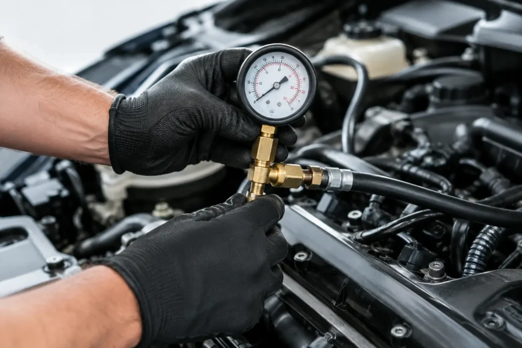
A fuel system can look perfect, start cleanly and still lose pressure when the engine is under load. That is why builders install fuel pressure gauge hardware during a new fuel-system build or when diagnosing lean running, hesitation, heat soak or inconsistent boost fuelling. A gauge gives you a direct view of what the pump, filter, regulator and lines are actually doing.
For street, drift and race cars, the job is not simply about adding a dial to a fuel line. The gauge type, fitting standard, mounting position and hose routing all matter. Get those details right and you gain a useful diagnostic tool. Get them wrong and you introduce a potential fuel leak into a high-risk area.
Why fuel pressure deserves a proper gauge
Fuel pressure is a key part of injector flow. An ECU can only deliver the expected fuel mass if the injectors see the pressure they were calibrated for. On a return-style EFI system, a falling pressure reading under boost or high rpm can point towards a restricted filter, undersized feed line, weak pump, voltage drop or regulator problem.
A carburettor setup has different pressure requirements, but the principle is the same. Too little pressure can create fuel starvation, while too much can overwhelm the needle and seat, causing rich running, poor hot starting or fuel overflow. Never assume a pressure figure from another build is right for yours. Use the engine, injector, carburettor and regulator manufacturer specifications as the baseline.
A gauge is also valuable during fabrication. Before the car sees road miles, it lets you verify that fittings seal, the regulator responds and the fuel system behaves consistently after the engine reaches operating temperature.
Choose the right gauge and mounting position
Mechanical gauges are simple and effective for checking pressure at the rail, regulator or carburettor feed. They are best suited to under-bonnet diagnostic use, where the dial can be inspected while setting base pressure or tracing a fault. A quality liquid-filled gauge can reduce needle vibration, although changes in under-bonnet temperature can affect its reading slightly.
For a permanent in-cabin display, use an electronic fuel pressure gauge with a remote sensor. The sensor remains in the engine bay or near the fuel system, while only electrical wiring enters the cabin. This is the safer route for a car that will be used hard on track, on drift days or on the road.
Avoid routing a live fuel line into the passenger compartment to feed a mechanical gauge. Even a well-built system can suffer from abrasion, vibration, a fitting failure or accident damage. Motorsport-grade hardware reduces risk, but it does not make fuel inside the cabin a sensible solution.
Gauge range matters too. Select a range that puts your normal operating pressure around the middle of the dial, rather than at the extreme end. A 0-100 psi gauge may work on a typical EFI setup, but a lower-range gauge often makes small pressure changes easier to spot. For carburettor systems, a low-pressure gauge is essential for useful resolution.
Parts and checks before you start
Match every component to the fuel type and operating pressure. Petrol, ethanol blends and race fuels can affect seals and hose materials differently, so confirm compatibility rather than relying on appearance. This is particularly relevant on E85 builds, where suitable hose, O-rings and fittings are non-negotiable.
You will normally need the gauge or pressure sensor, a suitable adaptor or gauge port, the correct thread sealant, spanners, a clean rag and a method of catching small amounts of released fuel. If you are adding an electronic gauge, you will also need switched 12V power, a good earth, illumination wiring where required and suitable terminals or connectors.
Check the fitting standards before ordering or assembling anything. NPT threads seal on the thread and may require a fuel-safe thread sealant. AN-style fittings seal on the flare, not the thread, and must not be treated with PTFE tape. Mixing standards by force is a reliable way to damage fittings and create leaks.
How to install a fuel pressure gauge
Depressurise the system first
Work on a cold engine in a well-ventilated space, away from heaters, grinders, cigarettes and any other ignition source. Keep a suitable fire extinguisher nearby. Disconnect the battery if you are working close to live electrical connections or modifying wiring.
Depressurise an EFI system using the manufacturer-approved method. Often this means removing the fuel-pump fuse or relay and running the engine until it stops, then cranking briefly. Some systems retain pressure even after this process, so loosen fittings carefully with rags in place. Carburettor systems may have lower pressure, but fuel can still spill quickly from a line or bowl feed.
Use a proper gauge port or adaptor
The cleanest solution is an existing service port on the fuel rail, if your rail has one and the thread matches the gauge or adaptor. Many aftermarket rails, regulators and fuel distribution blocks include dedicated 1/8 NPT ports for this reason.
If no port is available, install a purpose-made tee or adaptor in a suitable section of the system. On EFI builds, this is commonly close to the rail or regulator, depending on whether you need to monitor feed pressure, regulated rail pressure or another specific point. A reading taken before a restrictive component may look healthy while pressure after it falls away.
On a carburettor engine, place the gauge after the regulator if you want to confirm the pressure reaching the carburettor. Do not use a cheap universal plastic tee in a performance fuel system. Select a metal, fuel-rated fitting in the correct size and ensure it does not reduce the internal bore unnecessarily.
Seal threads correctly and support the assembly
Clean every thread and sealing surface before assembly. Apply only a small amount of fuel-safe liquid thread sealant to NPT threads, keeping it away from the first thread so no excess enters the fuel system. Tighten the fitting to the manufacturer specification where available. Over-tightening tapered threads can crack an aluminium rail, regulator housing or gauge body.
AN hose ends and adapters should be assembled cleanly, aligned without cross-threading and tightened with the correct spanners. Once the gauge is installed, make sure its weight is not hanging unsupported from a thin adaptor or flexible hose. Vibration can fatigue fittings over time, particularly on solid-mounted engines and track cars.
Mount and route with heat in mind
An under-bonnet mechanical gauge needs to be visible enough for setup work but positioned away from exhaust manifolds, turbochargers and moving belts. Do not mount it where the bonnet can strike it or where the dial is buried behind hot pipework.
For an electronic sender, use a rigid mounting point or supported fuel-system component. Avoid placing the sensor directly beside a major heat source where possible. Route wiring away from sharp edges, heat and ignition components, then secure it at regular intervals with proper clips or P-clamps. A loose wire or hose can eventually rub through even if it looked clear during installation.
Wire an electronic gauge properly
Supply the gauge from a fused, ignition-switched source so it powers on with the vehicle. Earth it to a known clean chassis or engine earth point, following the gauge manufacturer instructions. Poor earthing can create unstable readings that look like a fuel fault.
Keep sensor wiring away from high-current alternator cables, ignition leads and coils where practical. If your ECU can log fuel pressure, a compatible pressure sensor may be a better investment than a display-only gauge. Logged data lets you compare pressure against boost, rpm, injector duty and battery voltage after a hard pull, rather than relying on a quick glance at a dial.
Test for leaks before driving
Refit the pump fuse or relay, cycle the ignition to prime the system and inspect every connection under good light. Do not put your face close to a fitting and do not check for leaks with bare fingers. Use a clean paper towel around joints if necessary, then look for wetness or fuel smell.
Start the engine only after the system remains dry during priming. Watch the gauge at idle, then inspect again as the engine warms. On a vacuum-referenced EFI regulator, rail pressure may change at idle because manifold vacuum affects regulator reference pressure. That can be normal. The meaningful figure is often pressure relative to manifold pressure, so check the regulator setup instructions before deciding that a changing reading is a fault.
After a short road test, recheck all fittings. Heat cycles can settle seals and clamps, while engine movement may reveal a routing issue that was not obvious in the workshop.
Read the gauge like a diagnostic tool
A stable pressure at idle does not prove the system can supply enough volume at full load. If pressure drops as boost, rpm or load rises, investigate pump capacity, fuel filter condition, wiring voltage, line size, tank pickup and regulator flow capacity. On boosted applications, confirm that the regulator reference line is secure and connected to the correct manifold-pressure source.
If the needle flickers heavily, first rule out a poor gauge, trapped air or vibration. If an electronic reading jumps around, check the earth and sensor connector before replacing expensive fuel components. A gauge reports a problem, but it does not automatically identify the faulty part.
A correctly installed fuel pressure gauge earns its place every time you alter boost, injectors, fuel type or engine calibration. Treat it as part of the fuel system, not a cosmetic accessory: use quality fittings, mount it safely and let accurate pressure data guide the next move in the build.