

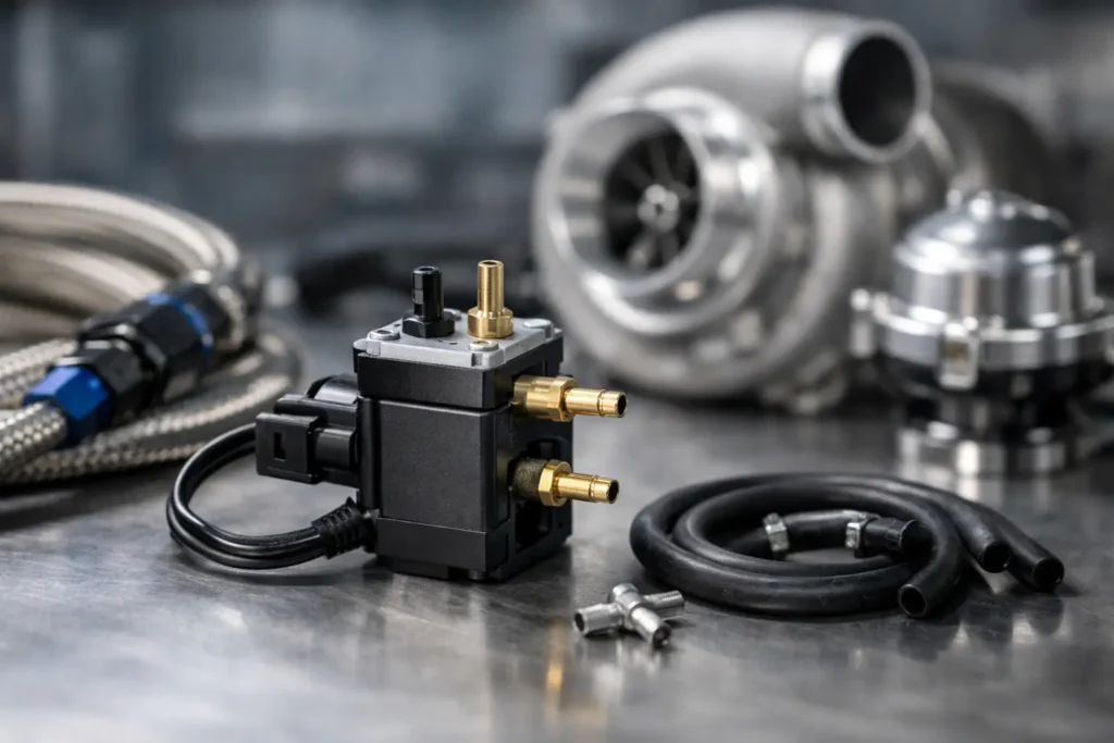
A turbo setup can have the right compressor, wastegate and ECU calibration yet still feel inconsistent if boost control is not right. This boost control solenoid guide covers the component that turns a basic wastegate system into a tunable, repeatable setup – provided it is plumbed, wired and calibrated correctly.
For street cars, drift builds and race applications, the goal is not simply maximum boost. It is controlled boost: pressure that reaches the target cleanly, stays there under load and responds predictably when ambient conditions, gears and engine speed change.
What a Boost Control Solenoid Does
A boost control solenoid is an electrically operated valve placed between a boost pressure source and the wastegate actuator or external wastegate. The ECU controls the valve using pulse-width modulation, usually called PWM or duty cycle. By opening and closing at a rapid rate, the solenoid changes how much pressure reaches the wastegate.
More pressure acting on the wastegate diaphragm opens the gate sooner, bypassing exhaust gas around the turbine and limiting boost. Reducing or delaying that pressure lets the wastegate stay shut longer, allowing the turbocharger to produce more boost.
The key point is that the wastegate spring establishes a mechanical minimum or base boost pressure. A solenoid generally adds control above that spring pressure. It should never be treated as a substitute for the correct wastegate spring, a sound exhaust-side setup or a safe ECU calibration.
A weak spring paired with an aggressive boost target can make control difficult, particularly on a responsive turbo or a high-flowing external wastegate setup. Conversely, a spring that is too close to the final target gives the ECU less authority to reduce boost if conditions demand it. The right balance depends on the engine, fuel, turbo size, intended use and available safety strategies.
Choosing the Right Solenoid for Your Build
Most aftermarket systems use either a three-port or four-port solenoid. A three-port unit is the usual choice for internal-gate road cars, external wastegates and many ECU-controlled turbo conversions. It can be configured as a bleed-style or interrupt-style system depending on the plumbing arrangement and the valve design.
A four-port solenoid provides more control authority and is often used where a large external wastegate, stiff spring combination or high boost target needs faster, more decisive control. It can help the ECU apply and release pressure more effectively, but it is not automatically the better option. A four-port valve is less forgiving of poor hose routing, incorrect ports or an unproven calibration.
Choose a motorsport-grade solenoid with compatible fittings, reliable coil operation and ports suited to your hose size. The physical installation matters as much as the specification. Mount it away from turbine heat, secure it against vibration and use short, heat-resistant vacuum hose. Long hose runs increase system volume and can slow the wastegate response, which makes boost control less precise.
Avoid using tired rubber hose, loose push-fit connections or random plastic T-pieces in a high-heat engine bay. A small leak in the reference line can create boost spikes, unstable control or a wastegate that does not open as expected. For serious builds, quality fittings and properly secured hose are cheap insurance compared with an overboost event.
Use a Clean Pressure Source
Take the boost reference from a reliable point on the compressor housing, compressor outlet pipework or inlet manifold, according to the wastegate and control strategy being used. The best location varies by setup, but the source must provide a stable, representative signal.
Do not share a critical wastegate reference line with devices that can distort the signal. Blow-off valves, fuel-pressure regulators and boost gauges may each need their own correctly positioned source. Keep the control circuit simple and easy to inspect.
Boost Control Solenoid Plumbing Basics
Port identification is the first rule. Different manufacturers label ports differently, often as COM, NO and NC, or with numbered ports. Never copy a hose diagram without checking the specific solenoid’s technical documentation. A valve that looks identical to another unit may use a different internal flow path.
On a typical three-port interrupt arrangement, boost pressure enters the common port, one port goes to the wastegate and the remaining port vents or returns to the intake side, depending on the system design. The ECU then manages pressure reaching the wastegate. In a bleed arrangement, the solenoid bleeds pressure away from the wastegate signal to hold the gate closed for longer.
Both methods can work well. Interrupt control is commonly preferred in performance applications because it can offer stronger control over the wastegate signal, while bleed systems can be straightforward on simpler builds. The best route is the one supported by your solenoid, wastegate and ECU strategy.
Before connecting the ECU, pressure-test the lines with regulated workshop air. Confirm that pressure travels through the correct ports when the solenoid is unpowered and powered. This takes minutes and can prevent an expensive first pull with the hoses reversed.
For external wastegates with both a lower and upper diaphragm port, the lower port normally receives the primary boost reference. The upper port may be used for advanced control, dome pressure systems or four-port configurations. Leave no port assumptions unverified: external wastegate diagrams differ across manufacturers and control methods.
Wiring and ECU Control
Most boost control solenoids use a two-wire coil. One wire receives switched, fused 12 V power and the ECU controls the other side by switching it to earth. This is known as low-side control. However, confirm the requirements of the ECU and solenoid before wiring, as some systems use a different approach.
Use a protected power supply, automotive-grade wire, quality terminals and a proper connector. Keep wiring away from exhaust heat and sharp edges, and provide enough slack for engine movement without leaving the loom unsupported. A poor earth, damaged connector or heat-hardened wire can look exactly like a tuning problem when the car is under load.
In the ECU, assign the correct output and enter the correct frequency for the valve. Solenoids are not all happiest at the same frequency. Too low or too high a setting can create noisy operation, weak control or excess heat in the coil. Start with the solenoid manufacturer’s recommended frequency, then calibrate duty cycle tables methodically.
Open-Loop Versus Closed-Loop Boost Control
Open-loop control uses fixed duty-cycle values based on engine speed, throttle position, gear or other inputs. It is simple and can work well on a stable setup, but it cannot actively correct for changes in air temperature, back pressure, fuel quality or load.
Closed-loop control compares actual manifold pressure with the target and adjusts duty cycle to correct the error. It is the stronger option for a properly mapped performance car, especially where boost targets vary by gear, fuel mode or traction requirement. It also needs a sensible base map. Closed-loop control cannot rescue an incorrectly plumbed solenoid, an inadequate wastegate or a system that spikes before the ECU can react.
Set conservative boost targets first. Log target boost, actual boost, duty cycle, throttle position, engine speed and, where available, wastegate or exhaust back-pressure data. Change one area at a time. Chasing a target by making large duty-cycle changes often produces oscillation and hides the real issue.
Diagnosing Common Boost Control Problems
If boost stays at base spring pressure, suspect a split hose, incorrect plumbing, an unpowered solenoid, a blocked vent or a duty-cycle table that is not commanding the valve. Test the solenoid electrically and mechanically before changing the calibration.
If boost spikes above target, inspect hose routing, wastegate size, actuator preload, turbine response and exhaust back pressure. A small internal wastegate can struggle to bypass enough exhaust gas on a free-flowing setup, while an external gate may need different spring pressure or control strategy. A solenoid cannot compensate for a wastegate that is physically undersized for the engine’s flow.
If boost hunts up and down, reduce overly aggressive closed-loop correction, check for leaks and shorten excessive reference hose runs. Confirm that the boost sensor reads accurately and that the wastegate moves freely. Sticky linkage, a damaged diaphragm or a kinked hose can create erratic behaviour that no amount of ECU adjustment will cure.
Heat-related faults are also common. A solenoid mounted close to the manifold may work during a cold test and fail after several hard laps or repeated road pulls. Mounting, thermal protection and hose quality deserve the same attention as the turbo hardware itself.
Build for Control, Then Tune for Power
A boost control system should be assembled as a complete circuit: correct spring pressure, suitable wastegate capacity, dependable reference lines, the right solenoid, protected wiring and a measured ECU calibration. ProSpeed Parts supplies the specialist hardware performance builds need, but the final result still comes down to fitment, testing and calibration discipline.
Treat every change to boost control as a controlled test, not a guess. When the mechanical system is sound, the solenoid becomes what it should be: a precise tool for delivering the boost your engine can use safely, consistently and lap after lap.