

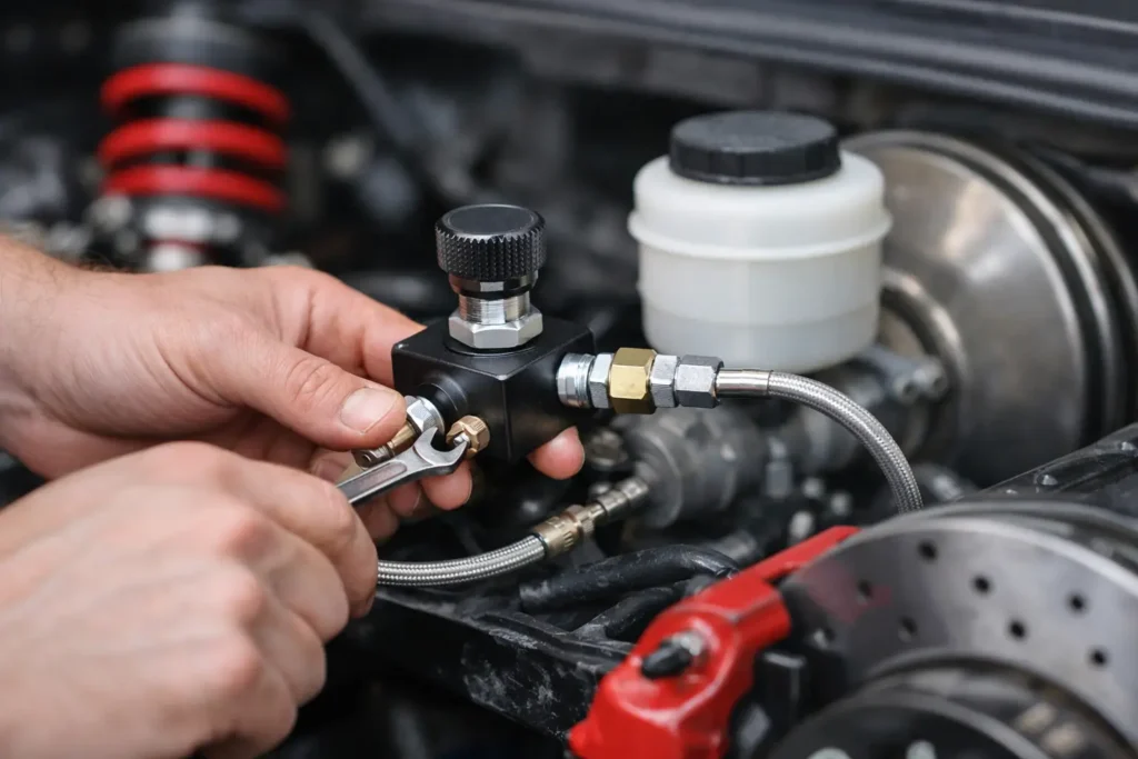
Fit the valve to the correct circuit
Knowing how to install a brake bias valve starts with understanding what it can and cannot do. An inline adjustable bias valve, more accurately called a proportioning valve, reduces hydraulic pressure to the circuit it serves. On most rear-wheel-drive track, drift and race builds, that means the rear brake circuit. It does not add front brake pressure, cure a poor brake package or make an unstable car safe at the turn of a knob.
The objective is controlled rear braking. Too much rear pressure causes premature rear-wheel lock-up, especially during heavy braking when weight transfers forwards. Too little rear pressure leaves stopping performance on the table and makes the front brakes work harder than they should. The correct setting depends on vehicle weight distribution, tyre compound, suspension geometry, brake disc and caliper sizing, and the grip available at each venue.
For a competition car with a front/rear split hydraulic system, an adjustable valve is a useful tuning component. For a road car retaining ABS, electronic brake distribution or a diagonal-split factory circuit, it is often the wrong modification unless the complete braking system has been properly engineered.
Confirm the system is suitable first
Before ordering fittings or cutting any hard line, identify the master cylinder layout. A conventional front/rear split system has one master-cylinder outlet feeding both front calipers and the other feeding both rear calipers. The valve belongs in the rear line, after the master cylinder and before the rear line divides at a T-piece.
A diagonally split system does not have one common rear circuit. Each hydraulic circuit typically operates one front and the opposite rear caliper. Fitting a single inline valve to one line can produce unequal rear braking and an unpredictable car. Do not improvise around this arrangement. A dual-master pedal box with a balance bar, or a correctly designed conversion, is usually the proper route for a serious motorsport build.
Also consider ABS. Restricting rear pressure upstream or downstream of an ABS hydraulic unit can interfere with the control strategy the car was designed around. If the car runs active ABS, retain the standard braking architecture unless a specialist has designed and validated the full conversion.
Parts and tools for a clean installation
Use motorsport-grade components that match the thread standard, flare style and pipe size already used on the car. British, metric and AN-based systems are regularly mixed on modified builds, and forcing an almost-correct fitting into a brake component is not acceptable.
You will normally need the valve, compatible inlet and outlet fittings, suitable hard brake pipe, pipe clips, a tube cutter, deburring tool, correct flare tool, line spanners and fresh brake fluid of the specified grade. A pressure bleeder makes the final stage quicker and gives a better chance of finding a small leak before the car leaves the workshop.
For fixed chassis runs, use quality steel or Kunifer hard line with properly supported clips. Flexible hose should only be used where movement is required, such as between the chassis and axle or suspension upright. Keep every hose clear of exhaust heat, sharp edges, rotating propshafts and full suspension travel. ProSpeed Parts supplies the fittings and fluid-system hardware needed for custom brake plumbing, but specification matters more than appearance here.
How to install a brake bias valve
Start with the vehicle securely supported on axle stands, wheels removed where necessary and the brake-fluid reservoir protected from spills. Brake fluid damages paint quickly, so keep water and clean cloths close by. Wear gloves and eye protection, then disconnect the battery if your work area is close to electrical wiring or the ABS unit.
Choose a mounting location that is rigid, protected and accessible. On a race car, the valve may sit inside the cabin near the driver for controlled adjustment between sessions, provided the rules allow it and the lines are safely routed. On a fast-road or drift car, a chassis-mounted position away from road spray and exhaust heat is often more sensible. Never mount it where a foot, harness or loose object can strike the adjuster.
With the rear circuit identified, measure the pipe runs before cutting anything. The ideal sequence is master cylinder or bulkhead outlet, bias valve, rear T-piece, then both rear calipers. Keep the plumbing simple. Every unnecessary adaptor is another potential leak point and another place for air to hide.
Cut the hard line squarely with a proper pipe cutter, then deburr the inside and outside of the cut. Slide the tube nut on before forming the flare – an easy mistake that costs time and pipe. Create the exact flare required by the fitting and inspect it closely. The flare should be even, centred and free from splits. Do not rely on thread sealant on brake flare fittings; the flare and its seat provide the seal.
Install the valve in the direction marked by the manufacturer. Most units have clear inlet and outlet markings, but do not assume the adjustment knob tells you the flow direction. Secure the valve body to a bracket or bulkhead using its mounting holes, not by letting the brake pipes carry its weight. Tighten fittings to the valve manufacturer’s specification using a line spanner to avoid rounding the nuts.
Before filling the reservoir, check every line through its full route. Look for tight bends, unsupported sections, contact with body seams and areas where the line could be crushed by a jack, wheel or suspension arm. A brake line may look clear with the car in the air but foul once the rear axle is at full bump, so inspect with the suspension compressed where possible.
Bleed, inspect and pressure-test
Refill only with new fluid that meets the master cylinder, caliper and intended-use requirements. Never mix incompatible fluid types. Bleed the system in the sequence specified for the vehicle or braking conversion, keeping the reservoir above the minimum level throughout. If the system has been fully opened, pressure bleeding is preferable, particularly on cars with long rear line runs.
Set the valve initially to its maximum rear-pressure position, following the maker’s instructions. This gives a baseline close to an unrestricted rear circuit. With the engine off, apply firm pedal pressure and hold it while another person inspects every fitting, flare and hose connection. There must be no weeping fluid, no fitting movement and no gradual pedal drop.
A hard pedal alone is not proof of a safe system. Check that both rear calipers apply and release correctly, that the handbrake mechanism is unaffected, and that brake lights still operate. On any road-going vehicle, confirm the modification remains compliant with applicable construction, insurance and inspection requirements before driving it on public roads.
Set brake balance where it is safe
Final adjustment belongs at a controlled test venue, not on a public road. Begin with the valve set for maximum rear pressure, then perform progressively harder straight-line stops on consistent, dry tarmac. A spotter, tyre marks, data logging and brake-temperature readings can all help, but the driver’s feedback still matters.
If the rear tyres lock before the fronts under threshold braking, reduce rear pressure in small increments. Repeat the test after each adjustment. The target is for the fronts to approach lock-up first, with the rear remaining stable and contributing meaningful braking force. On a rear-engined or heavily rear-biased car, the setting may be less restrictive than on a front-engined saloon. Rain, cold tyres, fuel load and tyre changes can all move the ideal balance.
For drift use, do not confuse service-brake bias with hydraulic handbrake performance. The foot brake must remain stable and predictable under high-speed braking before entry. A car that rotates because the rear brakes lock early is not faster – it is simply harder to place consistently.
The best brake-bias installation is the one you can inspect, service and tune with confidence. Use correctly matched hardware, retain a safe dual-circuit design and make changes one click at a time. That gives you a brake system that supports faster driving rather than demanding excuses for it.