

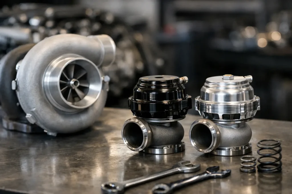
A wastegate that is too small does not simply make less power. On a hard-driven turbo build, it can turn a safe boost target into boost creep, excessive exhaust backpressure and a tune that cannot hold the number you mapped. Knowing how to size turbo wastegate capacity properly starts with one question: how much exhaust gas must bypass the turbine to maintain your lowest intended boost pressure?
That answer depends on the whole combination, not just engine capacity. Turbocharger size, turbine housing, exhaust manifold design, fuel type, camshafts, boost target and intended use all change the demand placed on the wastegate. A 44 mm external gate can be spot-on for one 2.0-litre street car and inadequate for another with a free-flowing tubular manifold, large-frame turbo and low boost target.
How to Size Turbo Wastegate Capacity
A turbo wastegate controls boost by routing exhaust gas around the turbine wheel. When the valve opens, it reduces the energy available to drive the turbocharger. The greater the amount of exhaust flow that needs diverting, the greater the wastegate valve area and flow capacity required.
The biggest sizing mistake is selecting a gate around the peak boost figure alone. High boost often needs less bypass flow because more exhaust energy is required to keep the turbine working hard. Low boost on an efficient, high-flow turbo setup is usually the difficult condition. The wastegate may need to divert a large proportion of total exhaust flow to stop the turbine accelerating beyond the requested boost level.
For that reason, size the system around the lowest boost pressure you genuinely plan to run, not the highest figure on the dyno sheet. If the car needs to run 0.5 bar for wet conditions, a low-boost map or a conservative running-in period, confirm the gate can control it there. A setup that holds 1.5 bar perfectly may still creep at 0.5 bar.
Start with the engine and power range
Engine displacement gives a useful starting point, but it is not a final answer. Larger engines produce more exhaust mass flow, yet a smaller engine operating at very high rpm with aggressive camshafts and a large turbo can demand just as much wastegate capacity.
Consider where the engine will operate. A drift car repeatedly held in the upper rev range needs stable control under sustained load. A drag application may tolerate a more specialised, high-boost arrangement. A fast-road car generally benefits from predictable low and mid-range boost control across changing gears, ambient temperatures and fuel quality.
Fuel also matters. Ethanol blends and race fuels can support more power and often produce exhaust conditions that differ from a typical pump-fuel setup. Do not assume a wastegate proven on a modest pump-fuel build will automatically suit an ethanol-fuelled combination making substantially more power.
Assess the turbine, not just the compressor
Wastegate sizing is closely tied to turbine flow. A restrictive turbine housing or small turbine wheel naturally absorbs more exhaust energy and may need less bypass capacity at a given boost target. A larger, freer-flowing turbine housing can require more bypass flow to control low boost because it passes exhaust gas efficiently.
This is why turbocharger specification matters. Two turbos with similar compressor ratings can behave very differently when paired with different turbine housings or A/R ratios. If the turbo manufacturer provides turbine flow information, recommended wastegate sizes or proven installation data, use it. Real application knowledge is more valuable than choosing a valve diameter by engine size alone.
Manifold configuration changes the result too. A divided manifold and twin-scroll turbine can retain strong pulse energy, making wastegate routing and sizing more critical. On a true twin-scroll setup, each scroll should normally have its own wastegate path if accurate control is required. Joining both scrolls before a single gate can compromise pulse separation and, in some combinations, limit bypass flow.
Choosing a Wastegate Diameter
Valve diameter is an easy comparison point, but it is not the complete story. Actual flow also depends on valve lift, port shape, seat design, actuator control and the way the gate is installed. Quality motorsport wastegates with similar nominal sizes may not flow identically.
As a general guide, a 38-40 mm external wastegate can work well on many moderate-output four-cylinder builds running sensible boost. A 44-45 mm unit offers more control margin and is often the safer all-round choice for larger four-cylinder engines, high-flow manifolds and builds that need low boost capability. A 50-60 mm gate is commonly used where bypass demand is high: large-frame single turbos, big-capacity engines, low base boost targets or applications where boost creep is unacceptable.
Those are starting points, not rules. Fitting the largest gate available is not automatically the right answer either. It can add cost, packaging difficulty and unnecessary fabrication work. The correct choice is the smallest high-quality wastegate that can reliably bypass enough flow for the lowest boost target, with a sensible safety margin.
On high-power six-, eight- and larger-cylinder builds, one large wastegate may be sufficient if the collector and take-off are designed properly. In other cases, two gates provide better access to exhaust flow and more consistent control. Twin gates are particularly common on divided housings, separate bank manifolds and exhaust systems where one valve cannot see both flow paths equally.
Wastegate Placement Can Make a Large Gate Act Small
A correctly sized gate can still fail if its take-off is poorly positioned. Wastegate flow wants the easiest route available. If the branch comes off the manifold at a sharp angle, is too small, or sits behind a restrictive merge, exhaust gas will favour the turbine instead. The result is boost creep even with a large valve fitted.
Position the wastegate take-off where it can access strong flow before the turbine entry, ideally from the collector or a well-designed merge. The branch should have a smooth transition and a diameter appropriate to the gate inlet. Avoid tight 90-degree turns, crushed bends and a short stub welded at an angle that forces gases away from the valve.
On a divided setup, retain separation as far as practical and give each wastegate path clean access to its respective scroll. For non-divided manifolds, a collector-mounted take-off generally gives the gate the best opportunity to bypass flow from all cylinders.
The outlet matters as well. A vent-to-atmosphere screamer pipe is often the least restrictive option, but it is loud and may not be road legal for your application. Recirculating the gate back into the downpipe is quieter and more road-friendly, but the merge must be positioned downstream with a shallow angle. Poor recirculation placement can create turbulence, backpressure and unstable boost control.
Match the Spring to the Control Strategy
The wastegate spring establishes base boost – the pressure the engine will run when the boost control solenoid is inactive or bypassed. Choose a spring pressure below your lowest required boost target, leaving enough room for the ECU or electronic controller to add boost reliably.
For example, if the car must run 0.7 bar at its lowest setting and 1.6 bar at its highest, a base spring around 0.4-0.5 bar may provide workable control authority. The exact choice depends on the boost control system, reference routing and gate diaphragm area. A spring that is too close to maximum target boost leaves little control range. One that is extremely soft can make the system harder to stabilise.
Use a boost reference source that reflects true manifold pressure, with short, heat-protected hose routing and secure fittings. A poor signal line, weak spring, leaking diaphragm or incorrectly plumbed solenoid can imitate a sizing issue. Before cutting and reworking a manifold, pressure-test the control hardware and verify the gate opens fully.
Validate the Setup Under Load
Wastegate sizing is proven on the road, track or dyno, not on the workbench. Begin with conservative boost control settings and log boost pressure, rpm, throttle position, exhaust backpressure where available, turbo speed where available and wastegate duty cycle.
If boost rises above target as rpm increases despite the controller reducing duty cycle or commanding the gate open, suspect insufficient bypass flow or poor gate placement. If boost is unstable or oscillates around the target, investigate the control strategy, spring selection, reference plumbing and exhaust reversion before assuming the valve is too small.
Do not tune around boost creep by simply reducing ignition timing, closing the throttle or accepting a higher target. Those workarounds can mask a hardware limitation and expose the engine, turbocharger and head gasket to unnecessary heat and cylinder pressure.
For serious street, drift and race builds, buy the wastegate as part of a complete exhaust-control system: suitable valve capacity, a properly designed manifold take-off, reliable springs, heat-resistant lines and ECU control that has been configured for the hardware. Build in margin now, then use testing to confirm the gate is doing its job when the engine is working hardest.